Opening: Why Temperature Stress Testing Matters Before the Road
Thermal runaway is often triggered by a chain of failures—micro-cracks, seal fatigue, insulation breakdown, solder joint fractures, or connector loosening—made worse by rapid temperature swings. That's why thermal shock testing is widely used to expose weak interfaces and mismatched materials early, before EV battery components ever reach the road.
A single undetected weak solder joint on a BMS board, a marginally sealed gasket, or a delaminating busbar adhesive can escalate from a minor defect under normal conditions to a catastrophic failure under real-world thermal cycling. The stakes in EV battery development are exceptionally high: safety recalls, warranty costs, and reputational damage all trace back to reliability decisions made during the design and validation phase.
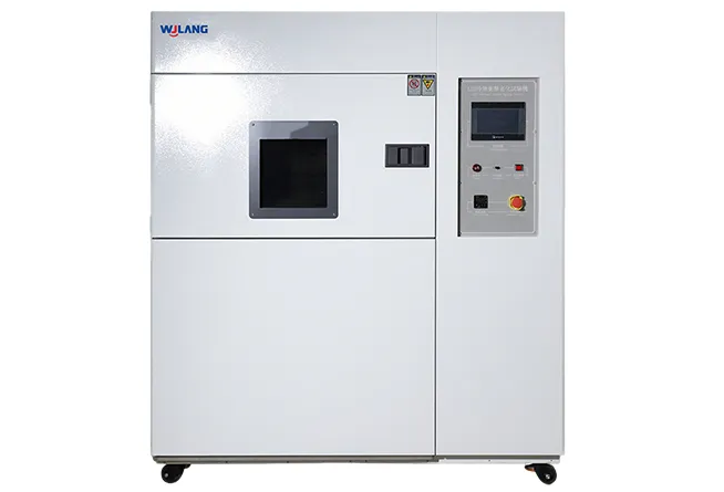
In this blog, we'll explain what thermal shock testing reveals about EV battery components, how it differs from thermal cycling, what chamber architectures exist, how to set up a proper test, and what to check when sourcing equipment from a thermal shock chamber China supplier. Whether you're a test engineer, procurement manager, or reliability lead, this guide will help you make more informed decisions.
Thermal Shock Testing 101: What It Detects in EV Battery Components
Thermal shock testing simulates the most aggressive scenario a component can face: an almost instantaneous shift from one temperature extreme to another. Unlike gradual warm-up or cool-down cycles, a thermal shock test moves parts from a hot zone (often +85°C to +150°C) directly into a cold zone (often −40°C to −65°C) within seconds. This rapid transition generates sudden mechanical stress at every material interface.
For EV battery components, this matters because batteries, modules, and their supporting electronics are assemblies of many different materials—metals, polymers, ceramics, adhesives, and composites—each with a distinct coefficient of thermal expansion (CTE). When temperature changes abruptly, materials expand and contract at different rates simultaneously. That differential stress concentrates at interfaces: solder joints, connector crimps, bonded surfaces, and sealing edges.
Common Failure Modes Thermal Shock Testing Accelerates
| Failure Mode | Likely Root Cause | What to Inspect Post-Test |
|---|
| Solder joint cracking | CTE mismatch between PCB and component | Visual inspection + X-ray; contact resistance measurement |
| Busbar delamination | Adhesive fatigue at metal-polymer interface | Peel strength; visual delamination check |
| Seal/gasket leakage | Rubber compression set; micro-cracks | Leak test (pressure decay or helium) |
| Insulation degradation | Thermal stress in polymer insulation layers | Insulation resistance (IR) measurement |
| Connector contact instability | Fretting corrosion at mating surfaces | Contact resistance measurement; insertion/withdrawal cycles |
| Cell holder cracking | Brittle polymer embrittlement at low temp | Visual inspection; dimensional check |
| PCB/BMS board trace fracture | Fatigue from repeated thermal expansion | Functional test; continuity check |
| Sensor assembly drift | Bonding failure between sensor and substrate | Output calibration verification |
Which Components Are Commonly Stressed?
The parts most vulnerable to rapid thermal shock in an EV battery system include:
Busbars and interconnects — especially at joints where copper or aluminum meets polymer or composite housings
High-voltage connectors and terminal blocks — where contact reliability is safety-critical
Sealing gaskets and O-rings — particularly for liquid-cooled modules where leaks create immediate hazards
Cell holders and module frames — often molded polymers that can embrittle at low temperatures
BMS boards and sensor PCBs — complex multi-material assemblies with many solder joints
Adhesive bonds and potting compounds — used to secure and insulate components throughout the module
Identifying which of these failure modes is most likely for your specific component—and designing the test to accelerate it—is the first step toward a meaningful thermal shock testing program.
Thermal Shock Testing vs Thermal Cycling: Which One Matches Your Reliability Goal?
These two test methods are often confused, and the confusion leads to mismatched test plans—either over-testing (wasting time and samples) or under-testing (missing real failure mechanisms). Understanding the practical difference is essential before specifying any equipment from a thermal shock chamber China supplier.
Thermal shock testing is defined by speed and extremes. The part moves from one pre-conditioned temperature extreme to another in as little as 10–30 seconds (transfer time). The thermal stress is primarily a sudden, intense mechanical shock at material interfaces. It's designed to find interface weaknesses quickly.
Thermal cycling is defined by controlled ramp rates and dwell times. The chamber temperature gradually rises and falls according to a programmed profile. Dwell times allow the part to fully soak to a uniform temperature. The cumulative stress simulates long-term expansion and contraction fatigue over many real-world use cycles.
When to Use Each Method
| Development Stage | Recommended Method | Primary Goal |
|---|
| Early design screening | Thermal shock testing | Quickly expose interface weaknesses; guide design changes |
| Design qualification | Both (shock first, then cycling) | Confirm shock survival; validate fatigue life |
| Production monitoring (HASS/ESS) | Thermal shock testing | Fast screening to catch manufacturing escapes |
| Long-term life modeling | Thermal cycling | Simulate years of field use; generate fatigue data |
| Regulatory compliance (e.g., IEC, AEC) | As specified by standard | Meet defined pass/fail criteria |
A Practical Decision Path
START: What is your primary reliability question?

├── "Do interfaces and bonds survive extreme rapid temperature shifts?"
│        └──► Use THERMAL SHOCK TESTING
│            (fast, aggressive, reveals weakness at interfaces)
│
├── "How many thermal cycles before fatigue failure?"
│        └──► Use THERMAL CYCLING
│            (controlled ramps, dwell soaks, fatigue life data)
│
└── "Both — design qualification for automotive supplier approval?"
        └──► Use BOTH IN SEQUENCE
            (shock screening first → cycling qualification second)
The short answer: if you need to find interface weaknesses fast and don't have 10,000 cycles to wait, thermal shock testing is the right tool. If you need to model long-term fatigue behavior under real-world temperature swings, thermal cycling fills that role. For automotive EV suppliers, both are typically required at different stages.
Thermal Shock Testing Chamber Types: Two-Zone vs Three-Zone and Why It Matters
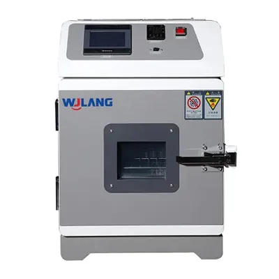
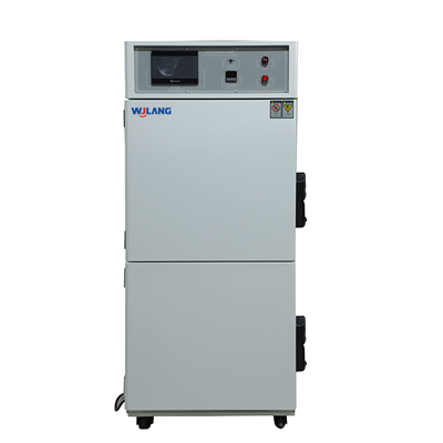
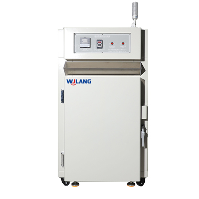
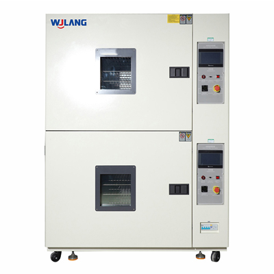
When you begin evaluating equipment from a thermal shock chamber China supplier, one of the first specification decisions is chamber architecture: two-zone or three-zone. This choice directly affects transfer time, temperature uniformity, test throughput, and the validity of your test results.
How Each Architecture Works
Two-Zone Thermal Shock Chamber: Two pre-conditioned zones are stacked or arranged side-by-side—one hot, one cold. A basket or elevator mechanism transfers the sample from one zone to the other. There is no intermediate ambient zone.
Three-Zone Thermal Shock Chamber: Adds an ambient/room-temperature zone between the hot and cold zones. This configuration allows three-stage transitions and can accommodate certain test standards that require ambient-temperature measurements between shocks. It also makes it easier to handle parts that need intermediate inspection between cycles.
Comparison: Two-Zone vs Three-Zone
| Feature | Two-Zone | Three-Zone | Best For |
|---|
| Transfer time | Very fast (5–15 sec typical) | Slightly longer (three positions) | Two-zone for fastest shock stress |
| Temperature range | Hot/cold extremes only | Hot / ambient / cold | Three-zone for standards requiring ambient dwell |
| Footprint | More compact | Larger | Two-zone for space-constrained labs |
| Throughput | Higher (simpler transfer mechanism) | Lower per cycle | Two-zone for high-volume production screening |
| Cost | Generally lower | Higher | Two-zone for budget-conscious procurement |
| Standards compatibility | Most automotive/EV standards | Standards requiring ambient step | Check your required standard first |
| Sample access | Less frequent without interrupting test | Easier mid-test access via ambient zone | Three-zone for parts needing intermediate inspection |
Matching Chamber Volume and Payload to Your Components
Beyond architecture, the internal volume and rated payload of the chamber must match your actual samples. For EV battery components:
Small components (connectors, sensors, PCBs): A 20–50 liter chamber may be sufficient
Module-level assemblies (cell holders, BMS boards, busbar assemblies): 100–300 liters typical
Full module or pack-level testing: 300+ liters; may require custom fixture engineering
Payload mass also affects temperature recovery time. A heavy thermal mass (dense metal fixtures + parts) requires more time for the chamber to recover to set-point temperature after transfer. Always ask the supplier for temperature recovery curves at rated payload—not just empty-chamber performance—when comparing specifications.
Thermal Shock Testing Setup for EV Battery Components: Fixtures, Sensors, and Pass/Fail Criteria
Having the right chamber is necessary but not sufficient. How you set up the test—fixtures, sensor placement, measurement plan, and pass/fail criteria—determines whether your thermal shock testing data is actually meaningful.
Why Fixtures Matter More Than Most Engineers Expect
A fixture is not just a mechanical support. In thermal shock testing, the fixture becomes part of the thermal system. A poorly designed fixture can:
Add thermal mass that slows temperature transfer to the sample, reducing effective shock severity
Shield portions of the sample from airflow, creating non-uniform temperature distribution
Introduce additional stress at contact points if the fixture material has a significantly different CTE than the sample
Reduce repeatability if the sample isn't held in a consistent position and orientation across test cycles
Best practices for fixture design in EV battery component testing:
Use low-thermal-mass materials (e.g., thin-wall aluminum or stainless frames) unless the fixture material is specified by the standard
Orient samples so airflow is unobstructed at critical interfaces (solder joints, sealing edges, connector mating faces)
Document fixture drawings and material specifications as part of your test record
Validate fixture performance by confirming sample temperature (measured at the part) versus chamber air temperature before starting the full test matrix
Sensor Placement Strategy
Temperature measurement at the air inside the chamber is not the same as temperature at the part surface or part interior. For EV battery components:
Place thermocouples or RTDs directly on the sample at the most thermally critical location (e.g., on a solder joint, at a seal interface, at the center of a busbar bond)
Use multiple sensor points on larger assemblies to confirm temperature uniformity across the sample
Log data continuously throughout the test, not just at end-of-cycle checkpoints
Record transfer time (from one zone to the other) as a critical test parameter, since it directly affects shock severity
Modern chambers from a reputable thermal shock chamber China supplier will include multi-channel data logging interfaces—confirm that your supplier can export time-stamped temperature data in a format compatible with your QMS or test reporting system.
Practical Pass/Fail Criteria for EV Battery Components
Pass/fail criteria should be defined before the test begins—not after. Typical acceptance criteria categories for EV battery component thermal shock testing:
| Inspection Type | What to Check | Typical Threshold |
|---|
| Visual inspection | Cracks, delamination, discoloration, seal damage | Zero visible cracks/delamination at defined magnification |
| Insulation resistance | IR between live and ground surfaces | ≥ specified minimum (e.g., ≥100 MΩ at 500 VDC) |
| Contact resistance | Connector or busbar joint resistance | Within ±X% of pre-test value |
| Leak test | Sealed module or housing | No detectable leak at specified pressure |
| Dimensional check | Warpage, dimensional change of housings | Within tolerance band |
| Functional test | BMS operation, sensor output | Within calibration limits |
Pre-Test Checklist
Before starting any thermal shock testing program on EV battery components, confirm the following:
PRE-TEST CHECKLIST
──────────────────────────────────────────────────────
□ Sample count defined (minimum per standard or DOE)
□ Samples pre-conditioned per applicable standard
□ Baseline measurements recorded (IR, contact R, visual, dimensions)
□ Fixture design reviewed and documented
□ Sensor placement validated with a short pre-run
□ Data logging configured and verified
□ Temperature extremes confirmed vs. chamber rated range
□ Transfer time confirmed vs. required specification
□ Post-test inspection criteria documented and agreed
□ Inspection intervals defined (e.g., every 50 cycles vs. end-of-test only)
□ Failure disposition process in place before test starts
──────────────────────────────────────────────────────
Thermal Shock Testing Procurement Checklist: How to Choose a Thermal Shock Chamber China Partner
Sourcing a thermal shock chamber is a significant capital equipment decision. For EV battery component validation, the chamber must be reliable, well-supported, and capable of meeting your test standards—not just the lowest price on a spec sheet. Here's how to evaluate a thermal shock chamber China supplier systematically.
Key Technical Specifications to Request
Always ask for a detailed datasheet and, when possible, a third-party calibration certificate or test report. Key parameters:
| Specification | What to Ask For | Why It Matters |
|---|
| Temperature range | Hot zone max; cold zone min (e.g., +200°C / −70°C) | Must cover your test standard extremes |
| Transfer time | Seconds from zone to zone (e.g., ≤10 sec) | Determines shock severity |
| Temperature recovery time | Time to return to set-point after transfer, at rated payload | Affects cycle time and throughput |
| Temperature uniformity | ±°C within the working zone at steady state | Affects test reproducibility |
| Temperature stability | ±°C over time at set-point | Affects soak validity |
| Internal volume | Liters (each zone) | Must accommodate your sample + fixture |
| Payload capacity | kg per zone | Must cover your heaviest assembly |
| Controller features | Programmable profiles, data logging, remote access | Affects test traceability and QMS integration |
| Safety protections | Over-temperature protection, refrigerant alarms, door interlocks | Required for safe lab operation |
Service and Support: What to Confirm Before Purchase
Technical support is often the differentiator between a good chamber and a frustrating one:
Commissioning support: Will the supplier send a technician for installation and initial calibration, or is it remote-only?
Spare parts availability: What is the lead time for common wear parts (door seals, heating elements, compressor components)?
Calibration documentation: Does the supplier provide calibration certificates traceable to national standards (e.g., CNAS, NIM)?
Software/firmware updates: Is the controller software upgradeable? Who provides support?
Documentation package: Full manual, wiring diagrams, maintenance schedule, spare parts list—confirm these are included
Compliance Alignment
EV battery component suppliers typically face layered requirements:
Internal test specifications from their own engineering standards
Customer requirements from OEMs (often referencing standards like IEC 60068-2-14, JEDEC JESD22-A104, AEC-Q200, or proprietary OEM specs)
Regulatory requirements depending on end market (UN 38.3, GB/T standards, UL, CE marking for the chamber itself)
Confirm with the supplier that their chamber's design and documentation support the specific standards you need to run. A reputable thermal shock chamber China supplier should be able to provide this alignment documentation as part of the quotation.
RFQ Template: What to Include When Requesting a Quote
RFQ — THERMAL SHOCK CHAMBER
──────────────────────────────────────────────────────────
□ Required temperature range: Hot ___°C / Cold ___°C
□ Required transfer time: ≤ ___ seconds
□ Required recovery time: ≤ ___ minutes at ___ kg payload
□ Internal volume required: ___ liters per zone
□ Maximum payload (mass): ___ kg
□ Chamber architecture preferred: □ Two-zone □ Three-zone □ No preference
□ Controller requirements: programmable profiles / data logging / remote interface
□ Applicable test standards: ___________________________
□ Required certifications (CE, UL, CNAS-traceable calibration): ___
□ Installation location: □ On-site commissioning required □ Remote support acceptable
□ Documentation required: □ Full manual □ Calibration cert □ Wiring diagrams
□ Annual calibration support: □ Required □ Self-managed
□ Budget range (optional): ___________________________
□ Timeline: Equipment needed by: ___________________________
──────────────────────────────────────────────────────────
Conclusion: Catching Failures Before They Become Field Problems
Thermal runaway prevention starts long before a battery pack is assembled. It starts at the material interface level—at every solder joint, every seal, every adhesive bond, every connector mating surface where two different materials meet and respond differently to temperature extremes.
Done correctly, thermal shock testing helps EV teams uncover reliability risks in connectors, seals, insulation, BMS boards, busbars, and module assemblies before they become field failures—or worse, safety incidents. Combining the right chamber architecture, proper fixture design, thoughtful sensor placement, and clear pass/fail criteria turns thermal shock testing from a checkbox exercise into a genuinely predictive reliability tool.
The choice of a thermal shock chamber China supplier is not just a procurement decision. It's a decision about whether your test results are trustworthy, your data is traceable, and your equipment will be supported over a 10–15 year service life.
Frequently Asked Questions (FAQ)
1. What is thermal shock testing and why is it used for EV battery components?
Thermal shock testing is an accelerated reliability test method that rapidly transfers a component from one temperature extreme (e.g., +125°C) to another (e.g., −40°C) within seconds. The sudden temperature change creates intense mechanical stress at material interfaces due to mismatched coefficients of thermal expansion (CTE). For EV battery components—which are multi-material assemblies including metals, polymers, ceramics, solder alloys, and adhesives—this test quickly exposes weak solder joints, delaminating adhesives, failing seals, cracking insulators, and unstable connector interfaces that might not appear during normal testing but would fail under real-world temperature swings. Using thermal shock testing early in the design and validation phase helps prevent costly field failures and reduces the risk of thermal runaway events linked to component-level reliability deficiencies.
2. What's the difference between thermal shock testing and thermal cycling?
The fundamental difference is the rate of temperature change and the primary stress mechanism. Thermal shock testing uses near-instantaneous temperature transitions (the sample moves from a pre-conditioned hot zone to a pre-conditioned cold zone in seconds), making the dominant stress mechanism a sudden mechanical shock at interfaces. Thermal cycling uses controlled ramp rates and temperature soaks, allowing the sample to reach a uniform temperature throughout—making the dominant stress mechanism fatigue from repeated expansion and contraction over many cycles.
For EV battery component reliability programs, thermal shock testing is typically used for early design screening and production monitoring (finding interface weaknesses quickly), while thermal cycling is used for qualification and fatigue life testing (simulating years of real-world use).
3. Which is better for my project: a two-zone or three-zone thermal shock chamber?
The best choice depends on your test standards and workflow:
Two-zone chambers offer faster transfer times, simpler mechanics, higher throughput, and lower cost. They are sufficient for the majority of automotive and EV battery component thermal shock standards (e.g., IEC 60068-2-14, AEC-Q200).
Three-zone chambers add an ambient temperature zone between hot and cold, which is required by some specific standards or useful when you need to perform mid-test inspections or measurements at room temperature without fully interrupting the test.
Start by checking your applicable test standard(s) for any reference to an ambient zone dwell. If no ambient zone is required, a two-zone chamber will typically deliver better performance at lower cost. If your standard specifies an ambient zone, or if your test plan requires intermediate room-temperature measurements, a three-zone configuration is the appropriate choice.
4. How do fixtures and payload mass affect thermal shock testing results?
Fixtures and payload mass have a direct impact on two critical test parameters: temperature transfer rate to the sample and chamber recovery time after transfer.
A heavy, dense fixture acts as a thermal buffer—slowing the rate at which the sample surface (and interior) reaches the target extreme temperature. If the sample doesn't reach the target temperature within the required dwell time, the thermal shock is less severe than specified, and the test may fail to accelerate the intended failure mechanisms. This leads to non-conservative (overly optimistic) results.
For EV battery component testing, best practices include:
Using low-thermal-mass fixture materials (thin-wall aluminum or stainless)
Validating that the actual sample temperature (measured by a thermocouple on the part) reaches the target within the required soak time
Requesting temperature recovery curves at rated payload—not just empty-chamber specs—from any thermal shock chamber China supplier before purchasing
5. What chamber specifications should I request when sourcing from a thermal shock chamber China supplier?
When evaluating a thermal shock chamber China supplier, request the following as a minimum:
Temperature range: Maximum hot zone temperature and minimum cold zone temperature
Transfer time: Seconds from zone to zone (this determines shock severity—faster is generally more aggressive)
Temperature recovery time: How long the chamber takes to return to set-point after sample transfer, measured at rated payload (not empty chamber)
Temperature uniformity and stability: ±°C within the working zone under load
Internal volume and payload capacity: Per zone, in liters and kilograms
Controller and data logging: Programmable test profiles, multi-channel temperature logging, data export formats
Safety protections: Over-temperature cut-offs, refrigerant leak detection, door interlock systems
Calibration documentation: Certificates traceable to national or international standards
After-sales support: Commissioning, spare parts lead time, software updates, on-site service availability
Always ask for test reports or calibration data at rated payload—not just empty-chamber performance—and confirm that the chamber's design supports the specific test standards you need to run.
Vietnam Wujinglang Technology
Vietnam Wujinglang Co., Ltd. is a high-precision reliability test equipment R&D & manufacturing provider, offering global environmental simulation and extreme test solutions for electronics, automobiles, aerospace, adhering to customer-first culture for sustainable development.
 English
  日本語
日本語  한국어
한국어  français
  Deutsch
  русский
  tiếng việt
  ไทย
ไทย  Malay
Malay 
 Know More