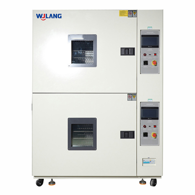
BMS hardware sits at the intersection of high current, fast switching, dense electronics, and harsh automotive temperature swings—conditions where small mechanical or electrical weaknesses can escalate quickly. Rapid thermal shock testing is designed to expose these latent issues early by forcing extreme temperature transitions that stress solder joints, connectors, PCBs, coatings, and housings. In this guide, you'll learn what thermal shock testing reveals, how it differs from thermal cycling, and what to evaluate when selecting thermal shock chamber manufacturers for EV BMS reliability work.
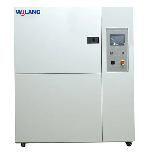
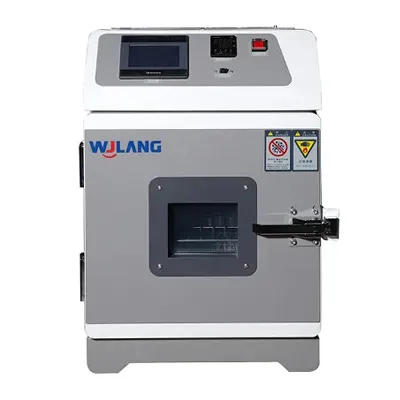
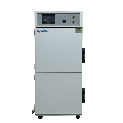
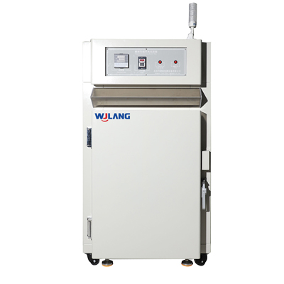
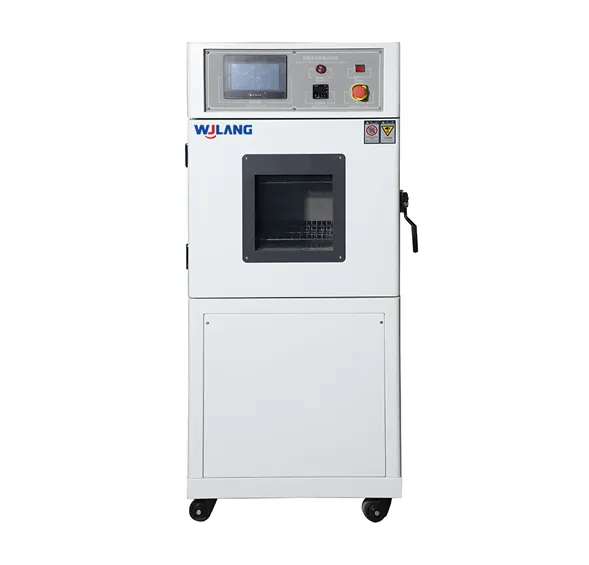
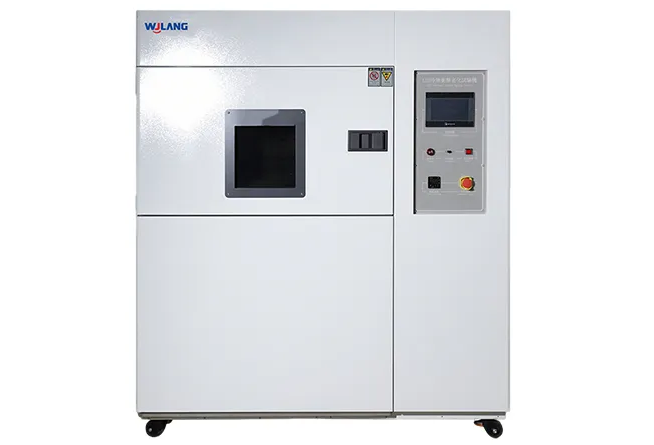
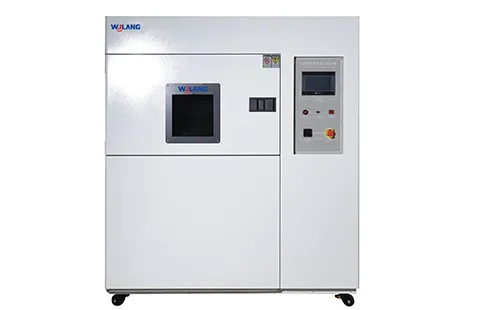
Two-zone thermal shock chamber with digital controller panel for EV BMS reliability testing — WJ Langtech thermal shock chamber manufacturers`
Thermal Shock Testing for BMS: What Failure Modes It Helps Uncover
BMS electronics carry signals that must stay accurate under extreme conditions. Rapid temperature transitions force differential expansion between dissimilar materials—and that's where hidden weaknesses become visible failures.
Common failure mechanisms exposed:
Solder joint cracking — repeated thermal stress fractures joints at component leads
Connector intermittency — contact surfaces micro-separate under thermal stress
Potting/seal delamination — encapsulants debond from PCB or housing surfaces
PCB warpage — laminate layers separate, causing trace failures or via cracking
Coating fractures — conformal coatings crack, exposing conductors to moisture
Why this matters for BMS specifically: even intermittent faults—a contact resistance spike, a sensor signal dropout, a momentary voltage glitch—can trigger false fault codes, disable cell balancing, or worse, miss a genuine thermal event.
| Component | Failure Symptom | Post-Test Inspection Method |
|---|
| PCB / Solder joints | Intermittent signal, open circuit | X-ray, dye-and-pry, continuity check |
| Connectors / Pins | Contact resistance increase | Four-wire resistance measurement |
| Sensors (temp/voltage) | Drift, offset error | Functional calibration check |
| Potting / Seals | Visible crack, moisture ingress | Visual + insulation resistance test |
| Housing / Enclosure | Warpage, gasket gap | Dimensional check, IP leak test |
Thermal Shock Testing vs. Thermal Cycling: Which Is Better for BMS Reliability Goals?
These two test methods are often confused but serve different purposes. Choosing the wrong one wastes test time and can leave real failure modes undetected.
The practical difference:
| Thermal Shock Testing | Thermal Cycling |
|---|
| Transition speed | Very fast (seconds to minutes) | Slow ramp (minutes to hours) |
| Primary stress | Instantaneous mechanical shock | Cumulative fatigue over many cycles |
| Best for | Design screening, interface failures | Durability, life simulation |
| Typical use stage | Early design validation | Pre-production, life testing |
A simple decision guide:
Does your BMS face sudden temperature exposure?
        ↓ YES                          ↓ NO
Use Thermal Shock Testing     Is fatigue life the goal?
(design screening)                ↓ YES
                           Use Thermal Cycling
                           (durability simulation)
                                  ↓ BOTH
                         Run shock first, then cycling
For most BMS programs, the recommended approach is shock testing first (to screen for interface failures at design stage), followed by thermal cycling (to validate long-term durability).
Thermal Shock Testing Chamber Types and Specs That Affect Test Severity
Not all thermal shock chambers deliver the same test severity. Understanding key specifications helps you match the chamber to your actual BMS test requirements—and ask the right questions of thermal shock chamber manufacturers.
Common architecture: Two-Zone Transfer The specimen basket physically transfers between a pre-conditioned hot zone and cold zone. Transition time (how fast the basket moves and the specimen reaches the new temperature) directly determines test severity. A slow transfer gives the specimen time to partially re-equilibrate—reducing the actual thermal shock the DUT experiences.
| Spec | Why It Matters for BMS | What to Ask the Supplier |
|---|
| Temperature range (hot/cold) | Must cover your BMS operating extremes | What are the verified min/max temps under load? |
| Transition / transfer time | Faster = more severe mechanical shock | What is the basket transfer time in seconds? |
| Recovery time | Affects throughput; slow recovery = fewer cycles/day | How long to recover setpoint after load insertion? |
| Temperature uniformity | Non-uniform zones create inconsistent results | What is the uniformity spec (±°C) at setpoint? |
| Payload heat mass limit | Heavy or large DUTs slow recovery | What is the maximum thermal mass per zone? |
| Safety protections | Battery DUTs carry risk; venting/fire detection needed | What safety interlocks are standard? |
Thermal Shock Testing Setup Best Practices for BMS Electronics
Even a well-specified chamber produces inconsistent results if fixtures, sensors, and acceptance criteria are not properly defined.
Fixture Design
Use low-thermal-mass fixture materials (thin aluminum or PTFE brackets preferred) to avoid shielding the DUT from the temperature transition
Ensure repeatable positioning—DUT must land in the same location every test to maintain consistent airflow exposure
Keep cable feedthroughs minimal and properly sealed to avoid creating a heat bridge
Sensor Placement
Always measure part temperature, not just air temperature—BMS boards with large ground planes or heatsink features may lag behind the chamber air
Use at least two thermocouples: one on the heaviest thermal mass of the DUT, one on the most thermally vulnerable component (typically a large BGA or connector)
Record sensor data throughout the full cycle, not just at endpoints
Pass/Fail Criteria
✅ Pre-Test Checklist
Thermal Shock Testing Procurement Checklist: How to Evaluate Thermal Shock Chamber Manufacturers
Selecting the right supplier is as important as selecting the right specification. When evaluating thermal shock chamber manufacturers, use this structured checklist:
Capability Requirements
✅ Chamber internal volume fits your largest BMS assembly with clearance
✅ Temperature extremes meet or exceed your test specification
✅ Transition time meets your standard requirements (e.g., <10 seconds for most EV applications)
✅ Automation options: programmable cycles, auto-transfer, unattended overnight operation
✅ Controller supports data export (CSV, direct integration) for test records
✅ Safety protections appropriate for battery DUTs (ventilation, sensors, interlocks)
Documentation and Support
✅ Calibration certificates traceable to national standards (NIST or equivalent)
✅ Maintenance records and recommended service intervals provided
✅ Spare parts availability confirmed for critical components (heating elements, seals, sensors)
✅ Technical support response time and local service coverage confirmed
✅ Test repeatability data available on request
For automotive labs specifically: ensure the manufacturer can provide documentation supporting your IATF 16949 or internal quality system requirements—calibration traceability and maintenance history are commonly requested during supplier audits.
Conclusion: Surface Failures Early, Before They Become Field Events
For BMS electronics, many serious field failures start as micro-cracks, intermittent connections, or material delamination that only become apparent after aggressive temperature transitions. Rapid thermal shock testing is the most practical way to surface those weaknesses during design validation—before they reach the field and contribute to thermal management failures or safety events.
The right outcome is a BMS that has been deliberately stressed, inspected, and confirmed—with the confidence that interface-level weaknesses have been found and addressed on your schedule, not the customer's.
FAQ
Q1: What is thermal shock testing, and why is it relevant to EV BMS reliability?
Thermal shock testing exposes a device to sudden, extreme temperature transitions—typically moving from a very cold zone to a very hot zone (or vice versa) within seconds. For EV BMS hardware, this simulates the sudden thermal stress the electronics experience during cold starts, fast charging, or pack-level temperature excursions. It is one of the most effective ways to find solder joint, connector, and interface weaknesses before they cause field failures.
Q2: What's the difference between thermal shock testing and thermal cycling for electronics?
Thermal shock testing uses very fast transitions (seconds) to create instantaneous mechanical stress at material interfaces. Thermal cycling uses slow, controlled ramps (minutes to hours) to accumulate fatigue damage over many repeated cycles. Shock testing is better for design screening; cycling is better for life simulation. Most rigorous BMS programs use both.
Q3: Which BMS components fail most often during thermal shock testing?
Solder joints (especially under large, rigid components like BGAs and capacitors) and connector interfaces are the most common failure sites. Potting and conformal coating boundaries are also vulnerable—especially where the coating transitions from a flexible to a rigid substrate. These are typically the first locations to inspect post-test.
Q4: What specifications should I compare when choosing thermal shock chamber manufacturers?
The most important specs are: temperature range (verified under load), transition/transfer time, temperature recovery time after DUT insertion, uniformity within each zone, and maximum payload thermal mass. For automotive lab use, also confirm calibration traceability, safety features appropriate for battery DUTs, and documentation support for quality system audits.
Q5: How should I design fixtures and thermocouple placement for consistent thermal shock testing results?
Use low-thermal-mass fixture materials to avoid insulating the DUT from the temperature transition. Position thermocouples on the DUT itself—at the heaviest thermal mass and at the most thermally sensitive component—not just on the chamber air probe. Consistent fixture positioning across all test samples is essential for repeatable results. Document thermocouple locations with photographs before every test series.
Vietnam Wujinglang Technology
Vietnam Wujinglang Co., Ltd. is a high-precision reliability test equipment R&D & manufacturing provider, offering global environmental simulation and extreme test solutions for electronics, automobiles, aerospace, adhering to customer-first culture for sustainable development.
 English
  日本語
日本語  한국어
한국어  français
  Deutsch
  русский
  tiếng việt
  ไทย
ไทย  Malay
Malay 
 Know More