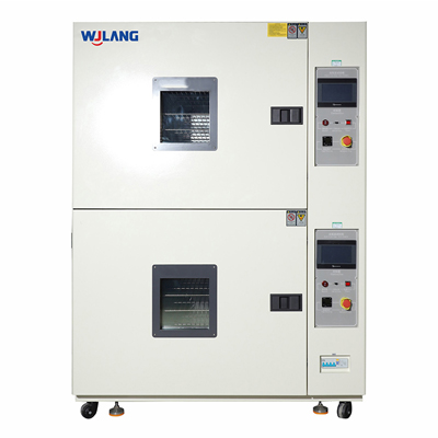
A thermal shock test can look simple on paper: expose a specimen to a hot condition, move it to a cold condition, repeat the sequence and inspect the result. In practice, the quality of the test depends on details that are frequently left undefined. Does dwell begin when the chamber air reaches the setpoint or when the specimen reaches temperature? Is the transfer time measured from door opening, basket movement or the moment the specimen enters the next zone? How much does the hot zone collapse after receiving a cold, heavy load? Does the test method require a rapid step change, or would a controlled thermal cycle be more appropriate? These questions determine whether the test creates the intended stress and whether results can be compared across laboratories.
This guide presents a practical method for designing a thermal shock profile. It is intended for reliability engineers, laboratory managers, quality teams and procurement professionals who need to translate a standard, customer requirement or internal qualification plan into a chamber configuration and an acceptance test. The emphasis is on the relationship among chamber air, specimen temperature, transfer mechanism, recovery, load and throughput.
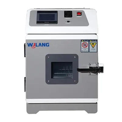
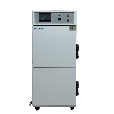
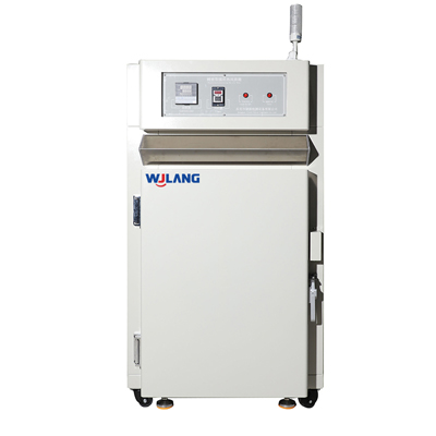
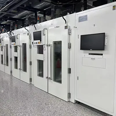
WJLANG publishes air-to-air thermal shock configurations with high-zone conditions up to 150°C, low impact options down to -65°C on selected models, storage-zone settings that may extend beyond the impact setpoints, transfer or switching designed within seconds, and temperature recovery within five minutes on specified systems. These values illustrate the performance categories that must be reviewed, but the final test profile should be based on the governing method and actual specimen.
What Is a Thermal Shock Test Profile?
A thermal shock test profile is a documented sequence of hot exposure, rapid transfer, cold exposure, recovery and repetition that defines how a specimen receives abrupt temperature stress.
The profile is more than two temperatures and a cycle count. It should identify the hot and cold conditions, tolerances, preconditioning, specimen operating state, dwell criteria, transfer time, recovery requirement, number of cycles, inspection points, allowed interruptions and data to be recorded. If any of these elements are ambiguous, two laboratories can follow the same headline requirement and produce different specimen temperatures, different stresses and different failure rates.
Thermal shock is used to accelerate stresses caused by unequal thermal expansion and contraction. Interfaces are especially vulnerable: solder joints, wire bonds, plated through-holes, glass-to-metal seals, adhesives, coatings, connectors, composite structures and assemblies made from materials with different coefficients of thermal expansion. Abrupt change can reveal cracks, delamination, leakage, loss of contact, parameter drift or intermittent behavior that may not appear during a slow temperature sweep.
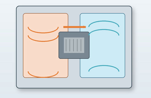
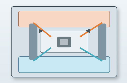
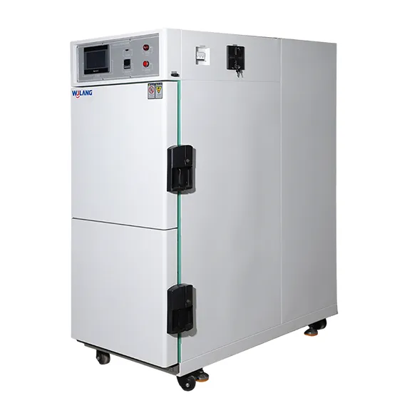
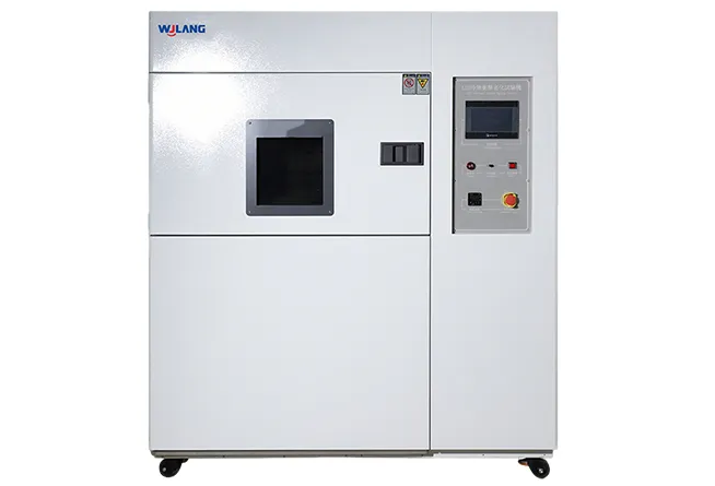
An air to air thermal shock chamber normally maintains separate conditioned zones so the specimen can be exposed to a rapid change without waiting for one workspace to heat and cool through the entire range. In a two-zone design, a basket or carrier moves the specimen between hot and cold zones. In a three-zone design, the specimen remains in a test space while dampers direct preconditioned hot or cold air through it. Both approaches can create severe transitions, but their load behavior, mechanical movement, airflow and maintenance requirements differ.
Thermal Shock Testing vs Thermal Cycling: Which Stress Is Intended?
Thermal shock testing creates a rapid step between established temperature environments, while thermal cycling changes temperature through a controlled ramp and usually subjects the specimen to a slower transition.
The terms are sometimes used interchangeably, but they should not be treated as the same test. Thermal shock emphasizes the transition and the steep thermal gradient that develops between the specimen surface and its interior or between joined materials. Thermal cycling emphasizes repeated expansion and contraction over programmed ramps and dwells. A product can pass one method and fail the other because the stress distribution is different.
Use thermal shock when the governing standard specifies transfer between hot and cold media or zones, when the field risk includes abrupt change, or when the engineering objective is to expose interface weakness quickly. Use a thermal cycle chamber when the method defines a controlled temperature rate, when the specimen must remain connected and undisturbed, or when the laboratory needs to reproduce a gradual environmental transition.
The distinction matters during procurement. A conventional temperature chamber may have an impressive cooling rate but still cannot reproduce a ten-second transfer between stabilized zones. A thermal shock chamber may create a transition that is too abrupt for a method requiring a linear ramp. Before selecting equipment, write one sentence that defines the intended stress: “The specimen shall be transferred from a stabilized hot environment to a stabilized cold environment within the specified transfer time,” or “The chamber air shall follow a controlled linear ramp between the specified temperatures.” That sentence prevents many later misunderstandings.
How Should High and Low Temperature Limits Be Selected?
Thermal shock temperature limits should come from the governing test method, product risk and material capability, with enough chamber reserve to recover after the specimen enters each zone.
The test limits are not always the same as the chamber’s storage-zone settings. A thermal shock system often preconditions the hot and cold zones beyond the required specimen exposure temperatures so that the zone can absorb the incoming load and recover quickly. For example, selected WJLANG two-zone models publish impact ranges with low-temperature options such as -65°C, -55°C or -45°C to 0°C and high-temperature operation from 65°C to 150°C. Their storage zones may be conditioned lower or higher than the impact setpoints. The exact reserve depends on load, airflow, refrigeration capacity and the acceptance requirement.
Do not select the most severe available temperature without an engineering reason. Excess severity can create failure mechanisms that are unrelated to field use or damage materials beyond the scope of the qualification. Conversely, a narrow range can miss the expansion mismatch that the test is intended to accelerate. The limits should be traceable to a standard, customer specification, design requirement or documented risk analysis.
Temperature tolerance must also be defined. A setpoint of 150°C does not mean every point around a large, loaded specimen is exactly 150°C. Specify whether the requirement applies to chamber air, a control sensor, distributed air sensors or thermocouples attached to the specimen. When the test is intended to compare designs, repeatability and measurement consistency are as important as absolute severity.
How Is Transfer Time Defined in a Thermal Shock Test Chamber?
Transfer time is the interval during which the specimen moves or the airflow switches from one conditioned zone to another, and its measurement start and end points must be explicitly defined.
A phrase such as “transfer within 10 seconds” is incomplete unless the measurement method is stated. In a two-zone basket system, possible start points include the command signal, the beginning of basket movement or departure from the first zone. Possible end points include entry into the second zone, completion of basket movement or door closure. In a three-zone damper system, transfer may refer to valve switching, airflow arrival or the time for the test space to cross a defined temperature threshold.
The engineering purpose is to limit the period in which the specimen is not receiving either intended environment. A long transfer allows the surface to drift toward room temperature and reduces shock severity. However, the mechanical mechanism must also avoid excessive vibration, impact or sample movement that could introduce an unrelated failure mode.
For factory acceptance, use a repeatable measurement. Record the control command, mechanism position and temperature response on the same time base where possible. Verify several transfers rather than one demonstration. If the specimen is fragile or connected to instrumentation, confirm that cable routing and fixtures do not interfere with movement.
WJLANG describes fast switching or movement within approximately ten seconds on relevant thermal shock platforms. Buyers should confirm the exact definition, load, model and acceptance method in the proposal. A supplier’s headline number is useful only when it matches the test requirement.
When Does Dwell Time Begin?
Dwell time begins at the event defined by the test method, which may be zone recovery, chamber-air stabilization or specimen-temperature stabilization rather than arrival in the zone.
This is one of the most consequential profile decisions. If a 30-minute dwell begins as soon as the basket stops, a heavy specimen may spend much of that time approaching the target temperature. If dwell begins after a specimen thermocouple reaches the required threshold, the complete cycle may be significantly longer but the specimen exposure is more consistent.
Three dwell definitions are common. The first is fixed time from transfer completion. It is simple and fast but may not account for different specimen masses. The second is time after chamber recovery. It ensures the air environment has returned to tolerance but still may not prove the specimen is conditioned. The third is time after specimen stabilization. It provides stronger control of specimen exposure but requires thermocouples and a clear stabilization criterion.
The governing method should determine the approach. If the method allows laboratory judgment, run a characterization study. Attach thermocouples to the slowest and most critical locations on a representative sample. Measure how long the specimen takes to enter the required temperature band after transfer. Use this information to establish dwell and to estimate throughput.
A practical mistake is to use the same dwell for a small printed circuit board and a dense metal assembly because both fit in the same chamber. The air may recover in minutes while the larger specimen takes much longer. The result is not merely a scheduling difference; it changes the thermal gradient and failure mechanism.
What Is Temperature Recovery and Why Does It Matter?
Temperature recovery is the time required for the receiving zone or test space to return to its specified tolerance after the incoming specimen disturbs the conditioned environment.
When a hot specimen enters a cold zone, it releases heat into the air, fixtures and refrigeration system. When a cold specimen enters the hot zone, it absorbs heat. The zone temperature moves away from setpoint and then recovers. Recovery time indicates whether the chamber has enough stored energy, airflow and heating or cooling capacity for the load.
Selected WJLANG three-zone specifications state temperature recovery within five minutes under defined conditions. That does not mean every specimen and every configuration will recover in five minutes. Large mass, high heat generation, blocked airflow, extreme setpoints and high ambient temperature can extend recovery. The quotation should define the representative load and the tolerance band used for the recovery measurement.
Recovery also influences dwell. If dwell begins only after recovery, a chamber with slow recovery increases cycle time. If dwell begins immediately, slow recovery reduces effective exposure. For high-throughput laboratories, even a one-minute difference per zone can accumulate over hundreds of cycles. Recovery should therefore be treated as both a test-validity parameter and an operating-cost parameter.
How Do Specimen Mass, Fixtures and Powered Operation Affect Thermal Shock Testing?
Specimen mass, fixture design and powered operation change thermal shock severity because they affect heat transfer, zone disturbance, airflow and the difference between air temperature and product temperature.
Mass is not the only factor. Material heat capacity, geometry, surface finish, internal air gaps and contact with the fixture all influence response. A thin aluminum plate may change rapidly, while an insulated plastic enclosure with internal components may respond slowly. A metal fixture can add more thermal mass than the specimen. Cables can conduct heat between the chamber and the outside. Multiple samples can shield one another from airflow.
Powered testing introduces heat generation and electrical interfaces. The chamber must remove the product’s heat in the cold zone and control local hot spots in the hot zone. The motion system must protect cables or use suitable feedthroughs. If the product is monitored continuously, the data acquisition system must be synchronized with the chamber record.
The RFQ should include specimen dimensions, mass, materials, quantity, fixture drawing, operating power, average and peak heat dissipation, cable count and any safety risk. A supplier can then evaluate basket capacity, airflow, refrigeration reserve, port design and mechanism load. A small environmental chamber may be ideal for compact passive components, but it should not be assumed suitable for a dense or heat-generating load merely because the sample fits inside.
Two-Zone vs Three-Zone Thermal Shock Chamber: Which Design Fits the Profile?
A two-zone chamber moves the specimen between separate hot and cold zones, while a three-zone chamber keeps the specimen stationary and switches conditioned airflow through a central test space.
| Decision factor | Two-zone basket or elevator design | Three-zone damper design |
|---|
| How shock is created | Specimen physically moves between hot and cold zones | Preconditioned hot or cold air is directed into a stationary test space |
| Specimen movement | Yes; fixture and cable routing must tolerate motion | No routine specimen movement during switching |
| Mechanical considerations | Basket capacity, lift mechanism, door sealing and movement repeatability | Damper sealing, airflow distribution and valve response |
| Powered monitoring | Possible but cable management can be more complex | Often easier for continuous connections because specimen remains stationary |
| Load behavior | Incoming specimen directly enters a preconditioned zone | Air is switched through the test space and must condition the specimen in place |
| Maintenance focus | Moving mechanism, guides, basket and seals | Dampers, ducts, seals and airflow balance |
| Best fit | Tests that explicitly require transfer and can tolerate specimen movement | Tests requiring stationary specimens, complex wiring or flexible airflow sequencing |
The choice should follow the method and specimen, not a general claim that one design is always better. A two-zone system provides a clear physical transfer between established environments and is widely used for component testing. A three-zone system can simplify instrumentation and reduce mechanical disturbance. Chamber volume, load, recovery, defrost strategy and maintenance access may be more important than the zone count alone.
Request a process diagram and a loaded performance explanation from the manufacturer. The proposal should state how the system creates the transition, how transfer is measured, how recovery is verified and how the specimen is supported. A comparison based only on internal volume and temperature range is incomplete.
How Can Thermal Shock Test Throughput Be Estimated?
Thermal shock throughput is estimated from transfer, recovery, specimen stabilization, dwell, cycle count, defrost and handling time rather than from dwell time alone.
Consider a simplified profile with a 30-minute effective hot dwell and a 30-minute effective cold dwell. If each transfer takes 10 seconds and the receiving zone requires four minutes to recover, the cycle is not simply 60 minutes. The dwell definition matters. If the 30-minute dwell starts after recovery, the cycle is approximately 68 minutes and 20 seconds before considering defrost, specimen stabilization or pauses. One hundred cycles would require more than 113 hours of continuous chamber time.
If specimen stabilization adds ten minutes in each zone, the cycle becomes approximately 88 minutes. One hundred cycles then require about 147 hours. This difference changes project scheduling, energy use and the number of chambers needed. A laboratory should characterize the actual specimen before committing to a production qualification schedule.
Throughput can be improved by selecting suitable chamber capacity, minimizing unnecessary fixture mass, arranging specimens for airflow, using representative but efficient dwell criteria, scheduling defrost intelligently and maintaining refrigeration performance. It should not be improved by shortening the test below the governing requirement.
How Should a Thermal Shock Profile Be Verified and Recorded?
Thermal shock verification combines chamber records, distributed air measurements, specimen thermocouples, mechanism timing and post-test inspection to show that the intended stress was delivered.
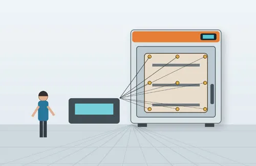
At minimum, record hot and cold zone temperatures, transfer events, alarms and cycle count. For profile development, add thermocouples at representative specimen locations and use a synchronized data logger. Verify the slowest thermal point, the most failure-sensitive interface and any area shielded from airflow. The number and location of sensors should be documented so the test can be repeated.
Inspect the specimen at planned intervals when early failure behavior matters. Electrical continuity, leakage, resistance, optical performance, dimensional change or other functional measurements may need to be monitored during the test. A final visual inspection alone can miss intermittent failures that recover at room temperature.
Review the chamber record for excursions. An alarm, door opening, power interruption or slow recovery should be assessed against the method. Do not automatically continue and treat the cycle count as valid. The laboratory procedure should define when cycles are repeated, when the test is restarted and how deviations are approved.
What Specification Mistakes Commonly Weaken Thermal Shock Testing?
Thermal shock specifications become weak when they omit measurement definitions, specimen conditions, loaded performance, acceptance tolerances or the distinction between air temperature and product temperature.
The first mistake is copying only the extreme temperatures from a standard. The transfer, dwell, cycle count, specimen state and tolerances may be equally important. The second is accepting a transfer-time claim without knowing how it is measured. The third is using empty-chamber recovery data for a heavy production load. The fourth is assuming chamber-air dwell proves specimen dwell. The fifth is neglecting fixtures and cables until after the chamber is built.
Another common problem is choosing thermal shock for every rapid-temperature requirement. Some products and standards require controlled thermal cycling. An excessively severe shock can create non-representative failures, while an insufficiently rapid cycle may not expose interface weakness. Equipment selection must follow the intended stress.
Procurement documents also weaken tests when they use vague phrases such as “high precision,” “fast recovery” or “suitable for electronics.” Replace these phrases with measurable conditions. State the setpoints, tolerance, load, transfer definition, recovery band, dwell trigger and records required during FAT.
Frequently Asked Questions About Thermal Shock Test Profiles
These questions summarize the profile decisions most likely to affect thermal shock severity, repeatability and equipment selection.
1. Is thermal shock the same as temperature cycling?
No. Thermal shock uses a rapid transition between established environments, while temperature cycling normally follows a controlled ramp. The correct method depends on the governing standard and the failure mechanism being evaluated.
2. Should dwell start when the basket stops moving?
Only if the test method defines it that way. Dwell may start after chamber recovery or after the specimen reaches a specified temperature. The trigger should be written into the procedure.
3. Why are storage-zone temperatures more extreme than test temperatures?
The zones may store extra heating or cooling capacity so they can absorb the incoming specimen load and recover to the required impact condition quickly.
4. Can a powered device be tested in a two-zone chamber?
Yes, but cable routing, connector movement, heat generation, basket load and continuous monitoring must be engineered. A stationary three-zone design may be easier for complex connections.
5. How many specimen thermocouples are needed?
The number depends on specimen size, thermal paths and critical locations. Use enough sensors to identify the slowest and most failure-sensitive points during profile characterization.
6. What information is needed for a thermal shock chamber quotation?
Provide the standard, hot and cold limits, transfer time, dwell definition, cycle count, specimen size and mass, fixture, heat load, wiring, cooling method, utilities, safety requirements and FAT criteria.
Conclusion
A defensible thermal shock test profile connects the intended failure mechanism to measurable temperatures, transfer, recovery, dwell, load, cycle count and verification records.
Start by confirming that abrupt thermal shock, rather than controlled cycling, is the correct stress. Define the high and low conditions and explain where they are measured. State how transfer time begins and ends. Decide whether dwell follows movement, chamber recovery or specimen stabilization. Characterize the real specimen so its mass, fixture, heat generation and wiring are included. Compare two-zone and three-zone designs against the method and instrumentation needs. Estimate throughput from the complete cycle, not dwell alone. Finally, use a loaded factory acceptance test and synchronized records to verify performance.
When these definitions are included in the RFQ, chamber selection becomes more accurate and test results become easier to repeat. WJLANG can review the profile and specimen information to recommend an appropriate standard or customized thermal shock system.
References
IEC 60068-2-14:2023, Change of temperature: https://webstore.iec.ch/en/publication/71503
U.S. Defense Logistics Agency, MIL-STD-883 document list: https://landandmaritimeapps.dla.mil/programs/MilSpec/ListDocs.aspx?BasicDoc=MIL-STD-883
ASSIST Quick Search, MIL-STD-202 Method 107 Thermal Shock: https://quicksearch.dla.mil/qsDocDetails.aspx?ident_number=280883
Vietnam Wujinglang Technology
Vietnam Wujinglang Co., Ltd. is a high-precision reliability test equipment R&D & manufacturing provider, offering global environmental simulation and extreme test solutions for electronics, automobiles, aerospace, adhering to customer-first culture for sustainable development.
 English
  日本語
日本語  한국어
한국어  français
  Deutsch
  русский
  tiếng việt
  ไทย
ไทย  Malay
Malay 

 Know More